
Technical Information
Got a question in mind ? You’re in the right place.
Here you’ll find the key technical information about our products. Whether you’re looking for recommendations, details, or procedures, everything you need is right here to support you with your machine.
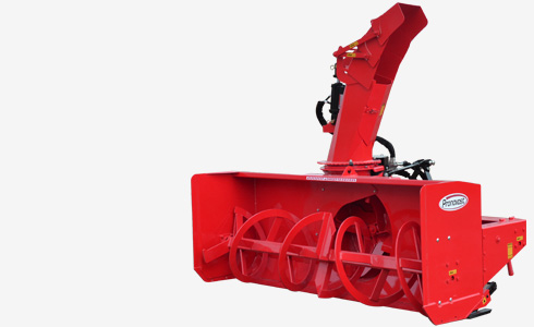
SNOWBLOWERS
Please refer to your user manual
For the most accurate and model-specific information, we strongly recommend consulting your user manual first. This document contains details specific to your machine. In case of any discrepancies, the information provided in the user manual takes precedence over that displayed on our website.
FINDING THE RIGHT SNOWBLOWER
It is important to choose a snowblower designed for use with the power, dimensions and weight of your tractor.
Click here to access our FINDING THE RIGHT SNOWBLOWER tool.
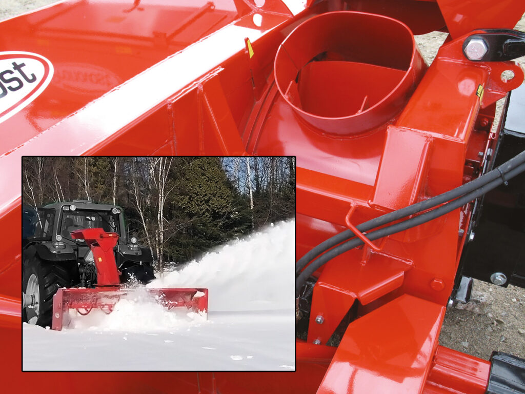
TRC = WITH ROTARY DRUM
The TRC designation, found in the name of certain models in the Pronovost, Large Ribbon Auger, and industrial snowblower series, indicates that the snowblower is equipped with a rotary drum.
The drum rotates via an Orbit motor. It is bolted on, making it replaceable, and is mounted on a UHMW bearing.
This practical feature allows snow to be blown without passing through the chute.
HAVE SPARE SHEAR BOLTS ON HAND
The shear bolt is designed to break in the event of a sudden blockage of the auger and/or rotor. This prevents damage to the mechanical components of the snowblower and of your tractor. Make sure that any replacement shear bolts you have meet the manufacturer’s recommendations.
Remember that when you use a PTO shaft that rotates at 1000 RPM, the shear bolt must be less resistant than when it rotates at 540 RPM. If your drive shaft has a hole for an original bolt at 540 RPM and you’re using it at 1000 RPM, be sure to use the weakened shear bolts.

Left picture : Weakened shear bolt.
Right picture : Regular shear bolt.
You can purchase shear bolts from your dealer.
SAFETY GUIDELINES
GENERAL SAFETY
- Careful operation is the best insurance against accidents. Carefully read the manual and follow all recommendations before operating your Snowblower. It is the owner’s responsibility to make sure that anyone who will operate the Snowblower will read the manual before operating the equipment.
- Familiarize with all controls and always be ready to stop the Snowblower quickly in case of emergency.
- Never let a child operate the Snowblower or leave the equipment unatended.
- Do not modify the Snowblower. Any non authorized modification may affect the efficiency and/or safety of the equipment and will automatically void the warranty.
- Never operate the Snowblower with defective parts or if damaged in any way. Have it repaired before operating.
- Make sure all fasteners are in place and properly secured or tightened. Refer to torque chart in the manual.
- Avoid wearing loose fitting clothing when working with the Snowblower. These could get entangled in moving parts of the equipment and cause accidents.
- Prolonged exposure to noise may damage hearing. Protect yourself by wearing adequate protection devices.
- Hydraulic fluids under pressure can damage your skin. Do not use your hands to locate a leak.
- Before the beginning of the snow season, inspect all areas where the Snowblower will be used and remove any object that may cause an accident and/or damage the equipment.
- Never operate the Snowblower in poor visibility or without proper lighting conditions.
SAFETY IN OPERATION
- Be sure there are no obstructions around the equipment and that no one stands near the equipment when in operation.
- Do not operate an engine in a confined or non ventilated area.
- Do not perform any adjustments, cleaning, maintenance or repairs with the engine running. The engine must be stopped and the P.T.O. disengaged. Preferably remove the key from the ignition.
- Wear adequate clothing when working in cold or windy conditions.
- Adjust skid shoes for proper ground clearance of scraper blade, especially in rough or soft ground conditions.
- Before operating, make sure the P.T.O. is properly installed and secured.
- Before starting the Snowblower, make sure the auger and drum areas are free of ice.
- Put P.T.O. control in neutral position before starting the engine.
- Keep hands, feet and clothing away from moving parts of the Snowblower. Stay away from the discharge chute.
- Before unplugging the chute, always disengage the P.T.O., stop the engine and relieve all hydraulic pressure.
- Do not operate in excessive inclined conditions. Be careful when turning in slopes.
- Never operate the Snowblower with missing guards or without protective devices in place.
- Do not operate your Snowblower near buildings, windows or any vehicules without prior and proper adjustment of the chute deflector.
- Never aim discharge chute towards people or animals. This may cause serious injuries.
- Always reduce operating speed in slippery conditions.
- Be careful when backing-up, make sure you have good visibility.
- Always be watchful for objects that may enter the Snowblower.
- If undue vibrations are felt, disengage the P.T.O., stop the motor and look for the cause of the vibration. Vibration is usually the indication of a problem.
- At the end of the operation, disengage the P.T.O., lower the Snowblower, put transmission in neutral, apply parking brake, stop engine and remove the key from the ignition.
SAFETY WITH MAINTENANCE
- Perform the Snowblower’s maintenance according to recommendations contained in the user manual.
- Stop engine and relieve all hydraulic pressure before doing any inspection, maintenance or repairs.
- Never perform any work under the Snowblower while it is supported only by the tractor’s hydraulic system. It must be completely supported by wooden blocks or other safe means.
SAFETY IN TRANSPORT
- On public roads, use proper safety lights and check local regulations.
- Be alert while driving on the road. Never carry any passengers.
- Always disengage P.T.O. while moving from one area of work to another.
- It is recommended to use both brake pedals simultaneously for better control.
- The recommended road speed should be such as to maintain full control over steering and braking.
- Be careful while backing up, make sure you have a good visibility.
SAFETY IN STORAGE
- Provide adequate supports to prevent any accidental overturning of the Snowblower.
- Do not let children play in the area where the snowblower is stored.
DECALS
- The safety decals are affixed wherever special safety precautions are indicated. Locate them on the machine and read them carefully. If a decal is damaged, lost or illegible, install a new one.
STARTING-UP THE SNOWBLOWER
- Check oil level in impeller gearbox. Adjust to the required oil level.
- Lubricate all points with a good quality multipurpose grease.
- Check chain take-up adjustment.
- Verify for adequate tightness of all fastening devices. Refer to torque chart in the user manual.
- Adjust skid shoes according to ground conditions.
- Following the installation of the Snowblower on the tractor, do not forget to lift the storage support.
- Make sure of a 540 RPM input to your snowblower.
- Check impeller adjustment.
- Adjust the descent speed of the 3 points hitch so it does not damage the snowblower when it touches the ground.
- Adjust the hydraulic flow in order to have a good control of the rotation speed of the chute.
MAINTENANCE OF THE SNOWBLOWER
- Wipe off all grease fittings with a clean cloth before adding grease in order to avoid injecting dirt and sand.
- Repair or replace damaged grease fittings.
- Lubricate all grease fittings every 8 hours of operation.
- Oil drive chain every 8 hours of operation.
- Lubricate P.T.O. shaft as indicated in the user manual. Pull out the P.T.O. and lubricate between the two tubes with low temperature grease. Drive line tubes must slide easily even in cold weather. Clean off old hardened grease and apply fresh grease as needed.
- Check oil level in gear box once a month. Adjust to the required oil level according to the drawing in the user manual.
- Check tension of drive chain every 24 hours of operation and adjust if necessary.
- Check for tightness of bearing collars every 48 hours of operation.
- Change gearbox oil once a year. Adjust to required oil level as per drawing in the user manual.
- Check all nuts and bolts once a year. If necessary use torque chart in the user manual.
- If the scraper blades are reversible, reverse them when they are worn.
- UHMW slides do not require lubrification except at the end of the season in order to prevent corrosion of steel components that are in contact with the UHMW material.
- When installing a new chain, it is strongly recommended to also change all the sprockets of your drive. The warn sprockets no longer have the proper pitch for your new chain; causes stretching and premature ware of the chain. Always route your chain according to the defined configuration.
If your snowblower is equipped with the optional speed reducer :
- After 10 working hours, the chain’s adjustment (if applicable) must be checked and then every 100 working hours.
- Check oil level in speed reducer once a month. Adjust to required oil level as per drawing in the user manual.
- Drain the oil of the speed reducer once a year. Adjust to the required oil level according to the drawing in the user manual.
- When using a 1000 to 540 RPM speed reducer, always make sure that you install either a 10 mm shear bolt or a 12 mm shear bolt that has been machined down to 3/8” (notched at shear point) depending on the category of drive line in use.
STORAGE OF THE SNOWBLOWER
- Store the Snowblower in a cool, dry place.
- Support the Snowblower with wooden blocks.
- Keep all piston rods in the retracted position. This will assure better protection against the elements.
- Clean your Snowblower.
- Thoroughly inspect all parts of the Snowblower. Replace or repair worn or defective parts.
- To avoid rust, touch-up or repaint if necessary.
- Lubricate all points before storage.
TROUBLE SHOOTING
FOR THE PTO SHAFT
| PROBLEM | POSSIBLE CAUSE | CORRECTION |
|---|---|---|
| Premature wear of U-joints and/ or bluish color of U-joint caps. | Insufficient lubrication. | Follow lubrication recommendations. |
| Replace defective U-joints. | ||
| Excessive working angle. | Make sure the Snowblower inlet face is perpendicular to the ground and if possible readjust 3-point hitch in order to position the Snowblower further away from tractor. | |
| Poor quality lubricant. | Use high quality lubricant. | |
| Gripping or premature wear of telescopic tubes. | Too much sliding under load. | Avoid raising Snowblower while in operation. |
| Tube overlap too short: minimum recommended is 6". | Readjust 3-point hitch in order to position the snowblower closer to the tractor. | |
| Insufficient lubrication. | Follow lubrication recommendations. | |
| Contaminants (sand, etc.). | Replace defective telescopic tubes. | |
| Damaged or jammed locking pin or bolt. | Pin or orifice contaminated by sand, ice, etc. | Clean and grease. |
| Drive shaft is too long, exerting pressure on locking device. | Readjust 3-point hitch in order to position the Snowblower further away from tractor or shorten tubes. | |
| Premature wear of guard tube bearing ring. | Lack of lubrication. | Follow lubrication instructions. |
| Wrong installation of guard chain. | Adjust chain to prevent interference between guard & equipment. | |
| Part of the guard in contact with the equipment. | Replace worn or damaged bearing rings. | |
| Cut or deformed safety guard tubes. | Tubes in contact with the equipment. | Eliminate any interference between tubes and equipment or tractor. |
| Replace damaged tubes. |
FOR THE SNOWBLOWER
| PROBLEM | POSSIBLE CAUSE | CORRECTION |
|---|---|---|
| The snow is not being thrown as far as usual. | Tractor's RPM is too low. | Raise P.T.O. speed to a minimum of 540 RPM. |
| Gap too wide between impeller blade tip and drum outlet wall. | Adjust impeller blades closer to drum outlet (1/8" to 3/16"). | |
| Insuffucient tractor HP. | Reduce back up speed. | |
| Frequent plugging of discharge chute. | Tractor's RPM is too low. | Raise P.T.O. speed to a minimum of 540 RPM. |
| Tractor's RPM is reduced too early with snow still in the Snowblower. | Make sure the Snowblower is completely empty before reducing RPM, especially on tractors with foot controlled RPM. | |
| Slippage of tractor's PTO clutch mechanism. | Repare clutch. | |
| Wet snow condition. | Reduce back up speed. | |
| Remove access panel. | ||
| The impeller will not rotate. | Shear bolt broken on main drive shaft. | Replace shear bolt. |
| The auger will not rotate. | Shear bolt broken on main drive shaft. | Replace shear bolt. |
| Broken drive chain. | Fix or replace chain. | |
| The rotating drum will not rotate. | Broken key on motor. | Replace the key. |
| Ice accumulation. | Remove ice. | |
| Wrong hydraulic connections. | Check hydraulic connections. | |
| The rotating drum does not hold in the central position when the snow is ejected by the chute. | Cushion valve setting too low | Reset cushion valve up to 1800 psi (max) |
| Tension of the spring in drum locking mechanism insufficient | Increase tension of spring by adding shim(s) | |
| The chute will not rotate. | Broken key on motor. | Replace the key. |
| Ice accumulation. | Remove ice. | |
| Wrong hydraulic connections. | Check hydraulic connections. |
WARRANTY
PRONOVOST warrants this product to the initial purchaser for the period of one year from the date of purchase against defects in materials and workmanship. We will replace or repair defective parts free of charge if they are returned to our factory in St-Tite, Quebec, Canada.
Transportation charges are the responsibility of the customer. This warranty is not transferable.
The hydraulic cylinders and motors that originaly equiped the snowblower are covered by the manufacturer’s warranty.
The P.T.O. shafts includes the warranty of the manufacturer. This only covers manufacturing defects, and is conditional on installation and use according to recommended standards.
All PRONOVOST original spare parts purchased are covered by a three (3) month warranty.
No guarantee is granted on wear parts.
This warranty becomes void and nul if the equipment is modified, if break downs are the result of an accident, if it is not operated according to manufacturer’s recommendations, damaged by negligence or if maintenance has not been carried out as specified.
Our obligation is limited to the replacement or repair of the defective part.
PRONOVOST does not accept any responsibility for direct or indirect consequential damages of any kind.
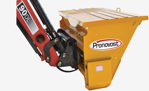
SAND AND SALT SPREADER
Please refer to your user manual
For the most accurate and model-specific information, we strongly recommend consulting your user manual first. This document contains details specific to your machine. In case of any discrepancies, the information provided in the user manual takes precedence over that displayed on our website.
SAFETY GUIDELINES
- Mandatory training prior to operation :
• Read and understand the entire manual.
• Possess all required knowledge and competence in regards to all aspects of operation.
• Prior to operating in the field for the first time, you must practice and be familiar with your spreader. Follow the procedure proposed in the user manual.
Note : the owner (person or legal entity) is responsible for the adequate training of operators. - Always conform to local regulations in force.
- Prior to any intervention on the spreader or when you are in close proximity, you must first :
• Disengage the hydraulic power.
• Lower the spreader to the ground.
• Turn off the tractor’s engine.
• Engage the parking brake.
• Release the hydraulic pressure
• Remove the key from the ignition and store it in a safe place. - Operate only when all guards are in place.
- Always follow the tractor manufacturer’s recommendations.
- Always follow the manufacturer’s recommendations of all other components from all other sources than Pronovost (E.g. hydraulic hoses, spreading material, …). Keep thier manuals and information sheets with the spreader manual.
- Always wear adequate clothes : no clothing that is too loose or torn, button cuffs and shirts, zip up coats, lace boots. Never wear a scarf or tie… They could catch on controls or moving parts of the spreader.
- Wear adapted gloves whenever installing or doing maintenance.
Note : The manufacturer of this equipment is not responsible for supplying any individual safety devices or protective clothing articles. - Access prohibited to all unauthorized persons.
- Never place your hand(s) near the rotative parts of the spreader.
- Never allow children to approach the spreader, whether it is operating or not.
- Never leave material stored in the bucket of the spreader. Material left in the spreader may freeze into a solid block and would require a thurough thaw, causing a substantial delay.
- Never attempt to operate when broken, nor with damaged parts. When the case is such, immediately stop operating the spreader.
- Never operate this equipment with impaired faculties “fatigue, alcohol, drugs…”.
- Do not spread while driving at high speeds.
- Never use the sand and salt spreader for snow removal (directly or indirectly).
- Never forcefully impact the ground with the sand and salt spreader.
- Never use the sand and salt spreader as a lifting device, nor for the transport of persons or material.
- Never use the sand and salt spreader for any other purpose than that intended; that is described in the user manual.
- Care must be taken when persons or animals approach the work site that the spreader is operating in:
• Adjust the tractor’s path and speed to keep the environment safe.
• At any time : be ready to stop the spreader and the tractor movement. - Always take care when operating in the vicinity of other vehicules, buildings and all other obstacles. Always take care when children or persons demonstrating unusual behavior or may not be aware of the danger that the spreader represents.
- Risks of entanglement, shock, shearing, cutting and crushing by the spreader crumbler and spreader dispenser rollers.
- Risk of entanglement and the crushing of fingers by the metering plate and by the closing of the cover.
- Risk of crushing a person who may become trapped in between the spreader and the tractor.
- Risk of serious injury if caught by the drive or driven sprockets present on the spreader.
- Prolonged exposure to excessive noise may cause hearing injuries or deafness. Wear hearing protection that meets with local regulations.
- Risk of crushing or serious injury to persons between the bucket and the ground. Never place yourself beneath the spreader bucket.
- By its nature, the spreader is used in places where the ground can be slippery and where there is a risk of falling. Wear adequate footwear with spikes.
NORMAL USE OF THE SPREADER
The Pronovost sand and salt spreader :
• Used to dispense salt or abrasives on a surface.
• Must be attached to a tractor or other appropriate carrier vehicle of sufficient power and weight; equipped with hydraulic outlets and lift system.
Normal use of this product as described above, is the only use for which it was designed. The manufacturer cannot be held responsible if used for any other purpose for which it was not intended.
Usual contraindications :
• Using the spreader for dispensing materials other than what is prescribed in this manual.
• Using the spreader for pushing or scraping snow or other material.
• Using the bucket for snow removal.
• Using the bucket for lifting or moving material.
TRANSPORT AND HANDLING
Our spreaders are designed to be handled with lifting equipment.
- Never attempt to handle the sand and salt spreader without the proper equipment : use lifting equipment that is designed for the task.
- When handling, the wearing of adapted gloves is recommended.
TRANSPORT WITH EQUIPMENT OTHER THAN THE TRACTOR
For long distance transport :
- Empty and clean the bucket.
- Disassemble the hydraulic connections.
- Disassemble the bucket from the tractor.
- Place the bucket on the means of transport (the surface should remain as horizontal as possible).
- Ensure the stability of the assembly, use cargo straps for securing the spreader.
LIFTING INSTRUCTIONS
Lifting operations are hazardous and requires constant vigilance when undertaken.
- It is prohibited to lift the spreader over persons.
- It is prohibited to approach the spreader unless it is on or in close proximity to the ground.
- Take weather conditions into consideration when lifting (high winds, heavy precipitations, poor visibility…). Postpone the lifting operation until conditions improve.
Use only approved lifting equipment of adequate capacity and in good working order. We recommend the use of slings and lifting beam. Adjust the length of the sling in a manner that the sand and salt spreader remains in the horizontal position.
TRANSPORT WHEN MOUNTED TO THE TRACTOR
- Always disengage the hydraulic pressure of the tractor and disconnect the hydraulic hoses.
- If applicable and depending on the type of quick attach, lift the bucket sufficiently high in order to avoid contact with the ground.
- Always respect speed limits and adapt the tractor speed accordingly. Always respect local regulations.
Note : safe travel speed can be inferior to posted speed limits. - Make sure that the bucket is empty during transport.
- Be attentive to other vehicles, especially if the bucket is wider than the tractor.
STARTING-UP THE SPREADER
VERIFICATIONS AND ADJUSTMENTS
Follow the verification and adjustment procedures below :
- Lubricate all points with a good quality multipurpose grease. Greasing locations are indicated by the respective grease decals.
- Verify the chain tensionner adjustment. An adjustment of the tensionner bolt may be required in order to maintain proper tension of the drive chain.
- Verify the dispenser plate setting. The bars of the dispenser roller should contact the teflon plate slightly. You may need to adjust the tension springs in order to get the correct setting. Do not over tighten so as to allow larger pieces of material to pass through the dispenser.
- Verify tightness of all bolts using torque guide chart in the user manual.
- Lubricate the chain regularly.
CHOOSING MATERIALS FOR SPREADING
Following suggestions in regards to materials recommended to spreading with the PRONOVOST spreader :
- The spreader will perform more adequately if material doesn’t have the tendancy to compact.
- Coarse salt is a good choice of material to use with the spreader.
- Crushed stone not exceeding 5/16″ is a good choice of material for use with the spreader.
- A mix of crushed stone (5/16″ net) and coarse salt is a good choice of material for use with the spreader.
- Stone dust containing particules inferior to 1/4″ is not a good choice since this material tends to cake.
- Sand that clumps when pressed will not give a good results, whereas sand that flows even after having been pressed will give a good results.
CONNECTING THE HYDRAULIC HOSES
Install and connect the hydraulic hoses conforming to good practices. Consult local regulations concerning hydraulic hose assemblies.
MOUNTING TO AND REMOVING THE SPREADER FROM THE TRACTOR
The various PRONOVOST quick attachment linkages are designed to allow salt and sand spreaders to be installed on most tractor models.
- The spreader must be mounted to a vehicle that is in good working order and must meet with local regulations in force.
- The tractor must be able to support the weight of the spreader and the horse power range of the tractor must match the one recommended for the spreader.
- Never undertake the mounting of nor the removal of the spreader without first immobilizing the tractor and turning off the engine.
- Follow bolt tightening recommendations in the torque chart as illustrated in the user manual.
- Mounting of the spreader onto the tractor must be done on a flat and level surface.
- Mounting a spreader changes the centre of gravity of a tractor. This will have an effect on the operation of the tractor and spreader assembly. Adding a counter-weight may be required.
INITIAL MOUNTING
When mounting for the first time, verify :
- The grease fittings,
- The hydraulic motor and connexions,
- The adjustment of the rollers drive chain,
- The bearings.
MOUNTING THE SPREADER’S QUICK HITCH TO THE TRACTOR
When installing the quick attach on the tractor, always follow the tractor manufacturer’s procedures and safety recommendations.
CONNECTING THE HYDRAULIC HOSES TO THE TRACTOR
Connect the hydraulic hoses to the outlets of the tractor in accordance with good operating practices, respecting the manufacturer’s specifications. Identify which control device on the tractor controls which movement on the spreader, especially if used with a hydraulic tilt attachment.
Adjust the tractor’s oil flow for each of the outlets (if available on your tractor model) to have good control of:
- Turning on the hydraulic motor,
- The oil flow sent to the hydraulic motor.
Note : if the tractor does not have the flow limiting feature, Pronovost offers unidirectional flow limiters. Contact your Pronovost dealer for further information.
REMOVING THE SPREADER FROM THE TRACTOR
- Make sure that the spreader will remain stable once you have disconnected it’s linkage from the tractor.
- Park and turn off the tractor following the procedure described in the safety rules.
- Disconnect the hydraulic hoses from the tractor.
- Disconnect the quick hitch from the tractor.
UTILIZATION OF THE SPREADER
A salt and sand spreader in operation represents danger for anyone approaching any of the moving parts of the spreader. The operator is responsible for safety in operation. Operator vigilence is of utmost importance.
SAFETY RULES
- Specific legal obligations can apply to the operation of a spreader in certain places (e.g. a signal man may be required for securing the work site).
- Never operate the spreader when there is poor lighting and/or poor visibility. Cease operations and wait for conditions to improve.
- Stop the spreader immediately if it begins to vibrate abnormally. Find the problem and fix it before resuming operations.
- As much as possible, get familiar with worksites prior to operations.
- Spread only on a well cleared of snow and unobstructed surface.
- Always use the tractor safety bars and fasten your seat belt.
- Use a counterweight if necessary to stabilize the tractor.
- Never operate a spreader in any area where the control of the tractor may be at risk (too steep a slope, irregular surfaces, risk of avalanche…).
- Never start the tractor engine if a hydraulic circuit is engaged. Put to the neutral position before starting the engine.
- Attention : snow banks and piles can hamper your field of view. Watch out for children playing nearby (they may be hidding behind a snow bank or in a tunnel, or sliding on a snow pile).
- A spreader in operation poses danger to any person in the vicinity. It is up to the operator to be vigilant and must stop the equipment immediately at the first sign of potential danger. Care must be excercised when in close proximity to persons, other vehicles, buildings as well as animals or any other structure or obstacle.
- It is recommended that both brake pedals (left & right) be locked together so braking will be simultaneous on both sides, thus preventing the tractor from skidding when the braking is sudden.
- Care when operating on slippery surfaces : reduce your speed and manouver carefully.
- Care when changing direction on a slope.
ACTIONS TO UNDERTAKE PRIOR TO INITIAL USE
Prior to initial use :
- Make sure the operator has the competance and the legal autorizations required to operate a tractor.
- Choose a spreading material according to manual recommendations.
- Make general start-up checks and adjustments
Verify:
- The greasing zerk fittings,
- The motor and hydraulic connections,
- The adjustment of the rollers chain
- The bearings
Follow the mounting instructions.
TRAINING AND GETTING FAMILIAR PRIOR TO OPERATING
- Read the entire manual and make sure that you understand all points regarding the operations relative to the use of a spreader.
- Before learning how to operate the spreader, the operator must first master the operating of the tractor (following the manufacturer’s recommendations) and possess all legal authorizations for it’s operation (drivers permit…).
- Proper training is a pre requisite for each person involved in the operation of a spreader.
- This training is valid only for the use of the tractor with which the training has been undertaken. If the spreader is mounted to a different tractor or is modified : the settings must be readjusted and you must reaquaint yourself with it’s behavior.
- Mounting a spreader changes the centre of gravity of a tractor. This will have an effect on the operation of the tractor and spreader assembly. A counterweight may be required.
Getting acquainted with the controls :
- Loading the bucket.
- Engaging and disengaging the hydraulic power.
- If necessary, raising and lowering the spreader, according to the quick attach.
- Adjusting the rate of dispensing.
- Handle the tractor while spreading.
- Immobilize the bucket and disengage hydraulic power quickly.
Finally, this training and familiarization does not cover the maintenance and repair work which requires specific skills and knowledge.
INSPECTION ROUND PRIOR TO EACH USE
Prior to each subsequent utilization, check the condition of :
- Cutting edge,
- Spreader dispenser and the UHMW plate,
- Guards (that they are in the proper position and with locking devices in place),
- The chain guard,
- Link pins,
- Lock pins,
- Safety decals,
- Hydraulic hoses and connectors,
- General condition of the spreaderer.
Proceed to the usual inspection round of the tractor. Remove ice and any debris from the spreader (E.g. stones, gravel…).
ADJUSTING THE FLOW OF THE SPREADER
Adjust the flow by slowly turning the knob of the flow-trottle.
CLOGGING
When operating, the material may clog; causing the rollers to stop or resulting in an improper spreading pattern. Probable causes :
- Debris may be caught in the bucket.
- The use of improper material.
- Inadequate hydraulic power.
- Malfunctioning hydraulic connectors.
Before resuming operations, you must free up the rollers and loosen up or change the material.
- Never place your hands near the rollers, nor in the bucket.
- Risk of entanglement on and being pulled into the rollers; causing serious injury or death.
Turn off the tractor engine following safety instructions.
Use a wooden or plastic stick to loosen the material : never put your hands in the bucket, nor near the rollers ! Inspect the bucket and mechanism for unwanted objects and check for damage. Repair any damages that may have occured before putting back into operation.
ACCIDENTAL COLLISION
In the event of a collision with a person, or an animal, or another vehicle :
- Protect :
- Immediately stop the spreader and the tractor.
- Turn off the engine.
- Secure the site and yourself.
- Alert :
- Contact emergency services and follow their instructions.
- Rescue :
- If you are capable and that you don’t put yourself at risk : rescue victims following instructions given by emergency services.
ONCE YOU HAVE FINISHED OPERATIONS
Empty and clean the bucket and inspect to insure that all is in good working order.
MAINTENANCE OF THE SPREADER
GENERAL RULES
- Undertake maintenance as prescribed in this manual. Specific knowledge and qualifications are required for carrying out maintenance procedures. The reading of the manual alone is not enough.
Note : A lack of proper maintenance may lead to the cancellation of the warranty offered by Pronovost. - Never work on the spreader unless the tractor is turned off and immobilized according to the procedure described in the rules of safety.
- When doing maintenance, it is recommended to wear gloves that are adapted to the task. Other protective wear or devices may be required depending on the task undertaken : refer to good practices.
- Never place fingers, hands nor any other part of your body between the spreader and the ground if it is only supported by the hydraulic system. The spreader must be totally supported on blocks or any other means that assures stability.
- Always put back into place all guards and protective devices once you have terminated maintenance operations. Replace any damaged guard or devices with original parts.
- Always conform to torque values shown in the user manual.
- If you detect any oil leak, immediately halt all operations until the problem has been fixed.
- Never try to localize a leak with your bare hands, nor any other part of your body. Use proper protective devices adapted to the situation.
- When lubricating the bearings, never inject any more than one stroke of the grease gun, otherwise you may rupture the bearing seals.
- If your spreader bucket has a lid, make sure the prop is hooked properly if you have to do maintenance inside the bucket
We recommend the use of original Pronovost replacement parts unless approved by our service department. Parts from other sources may not be compatible and may lead to the degradation of performance, or failure, and consequently voiding the warranty.
Refer to the user manual for the maintenance table.
REGULAR MAINTENANCE
General lubricators
- Wipe grease fittings with a clean cloth to prevent injecting dirt or sand and use a good quality grease. Repair or replace any damaged fittings.
UHMW plate wear inspection
- Check the dispenser UHMW plate wear.
- The teflon plate may wear prematurely if the dispenser is adjusted too tightly.
Bolts
- Verify the tightness of all bolts. For torque values, refer to the user manual.
Hoses and hydraulic circuit
Verify :
- The absence of leaks,
- The good condition of all the elements of the circuit,
- Tightening of the couplings,
- That the hoses are routed in a way to prevent excessive friction.
STORAGE OF THE SPREADER
STORAGE LOCATION
- The spreader must be stored in a fashion as to assure it’s stability and to prevent accidental overturning.
- The bucket must be emptied before storage.
- It is preferable to store the spreader in a cool and dry location, on wooden blocks several centimetres thick in order to prevent corrosion.
END OF SEASON MAINTENANCE
Prior to storing the spreader at seasons end :
- Empty and clean off all dirt to prevent corrosion…)
- Undertake end of season maintenance as defined in the user manual.
- Inspect the spreader for damages and replace any of the parts that are bent, broken or worn.
- Touch up damaged paint to avoid rusting.
- Lubricate the salt and sand spreader before storage.
TROUBLE SHOOTING
| PROBLEM | POSSIBLE CAUSE | CORRECTION |
|---|---|---|
| The crumbler does not turn. | The hydraulic pressure is insufficient. | Check the hydraulic pressure. |
| Oil can not circulate in the hydraulic circuit. | Check if the hydraulic connectors are properly connected. | |
| Object blocking the system. | Reverse the crumbler's rotation. | |
| The drive chain is not working. | Reinstall the chain if not defective. | |
| Install a new chain if defective. | ||
| Tighten the drive chain. | ||
| The flow adjuster is closed. | Open the flow adjuster. | |
| The amount discharged is too large. | The adjuster is open too much. | Reposition the arm to close the opening. |
| The springs are not tight enough. | Tighten the springs. | |
| The amount discharged is too little. | Object too big in the feeder. | Reverse the feeder rotation to release the objects. |
| Open the feeder to allow passage of objects. | ||
| The adjuster is not well positioned. | Reposition the arm to open the opening. | |
| The springs are too tight. | Loosen the springs. |
WARRANTY
PRONOVOST warrants this product to the initial purchaser for the period of one year from the date of purchase against defects in materials and workmanship.
We will replace or repair defective parts free of charge if they are returned to our plant in St-Tite, Quebec, Canada.
Transportation charges are the responsibility of the customer. This warranty is not transferable.
All PRONOVOST spare parts purchased are covered by a three (3) month warranty.
No guarantee is granted on wear parts.
This warranty becomes void and nul if the equipment is modified, breaks down as the result of an accident, is not operated according to manufacturer’s recommendations, damaged by negligence or if maintenance has not been carried out as specified.
Our obligation is limited to the replacement or repair of the defective part.
PRONOVOST accepts no responsibility for direct or indirect consequential damages of any kind.
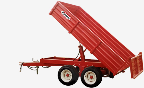
DUMP TRAILERS
Please refer to your user manual
For the most accurate and model-specific information, we strongly recommend consulting your user manual first. This document contains details specific to your machine. In case of any discrepancies, the information provided in the user manual takes precedence over that displayed on our website.
SAFETY GUIDELINES
GENERAL SAFETY
- Careful operation is the best assurance against accidents. Carefully read the user manual and follow all recommendations before operating this equipment. It is the owner’s responsibility to make sure that anyone who will operate the Trailer will read this manual before operating the equipment.
- Do not modify the equipment. Any non authorized modification may affect the efficiency and/or safety of the equipment.
- Never operate the equipment with defective parts or if damaged in any way. Have it repaired before using it.
- Make sure all fasteners are in place and properly secured or tightened. Refer to torque chart in the user manual.
- Hydraulic fluids under pressure can damage your skin. Do not use your hands to locate a leak.
SAFETY IN OPERATION
- Be alert while driving on the road. Never carry
passengers. - WARNING! Do not overload your trailer, do
not exceed the load capacity indicated in the user manual. - Be sure there are no obstructions around the equipment and that no one stands near the equipment when in use.
- Do not operate an engine in a confined or non ventilated area.
- Do not perform any adjustments, cleaning, maintenance or repairs with the engine running on the towing vehicule. Preferably remove the key from the ignition.
- Be careful when backing-up, make sure you have good visibility.
- In the case of a Highway Service Trailer, make sure the suspension and lights are all functioning properly.
- Do not forget to unlock the proper panel before dumping.
- Always travel at a safe operating speed following regulations and common sense. In the case of agricultural service tires, follow the manufacturer’s specified safe speed. Never exceed the speed that permits full steering and braking control at all times.
SAFETY WITH MAINTENANCE
- Perform maintenance according to recommendations contained in the manual.
- Before performing any work under the raised platform, always install the safety support provided.
- If the trailer is hooked up to the tractor while performing maintenance work, make sure the engine is not running and preferably remove the ignition key.
SAFETY IN TRANSPORT
- On public roads, use proper safety lights, make sure they work properly and check local regulations.
- Make sure coupler is the same size as the ball hitch and well secured.
- Make sure safety chains cross under the coupling mechanism and properly attached to towing vehicle.
- Be alert while driving on the road. Never carry passengers.
DECALS
- The safety decals are affixed wherever special safety precautions are indicated. Locate them on the equipment and read them carefully. If a decal is damaged, lost or illegible, install a new one.
STARTING-UP THE DUMP TRAILER
- Lubricate all grease fittings with a good quality multiuse grease.
- Lubricate panel release mechanism, front and rear with good quality oil.
- Adjust tire pressure to manufacturer’s specifications.
- Install wheels on hubs.
WARNING: Wheel lug nuts must be applied and maintained at the proper torque levels to prevent loose wheels, broken studs, and possible separation of the wheel(s) from your trailer. The lug nuts on the wheels of your trailer must be maintained according to the torque values listed in the chart contained in this section. Over torquing and under torquing wheels are both dangerous.
WARNING: Towing, especially during the break-in period, can cause wheel lug nuts to loosen. Failure to maintain proper torque of the wheel lug nuts could lead to separation of the tire and wheel while driving, possibly resulting in property damage or personal injury. Be sure to use only lug nuts matched to the cone angle of your wheel, usually 60° or 90°.
The proper procedure and sequence for attaching the wheels and torquing lug nuts is as follows:a- Start all nuts by hand to avoid cross threading.
b- Tighten the nuts slightly.
c- Tighten the wheel nuts following the tightening sequence outlined in the user manual.
d- Torque the wheel lug nuts before the first road use and after each wheel removal. Check and re-torque after the first 16, 40 and 80 kilometers (10, 25 and 50 miles) and adjust if required. Check periodically thereafter without exceeding 50 hours of use between the verifications.
Check the wheel lugs after winter storage, before starting a trip or following extensive braking. Perform maintenance periodically as indicated above. - Install panels.
- Install all hydraulic hoses and fittings compatible with your equipment.
- Verify for adequate tightness of all fastening devices. Refer to torque chart in the user manual.
- Operate the hydraulic system a few times, raising and lowering the platform in order to remove any trapped air in the system. Then check the oil level in the tractor’s hydraulic oil reservoir.
- Do not forget to unlock the proper panel before dumping.
MAINTENANCE OF THE DUMP TRAILER
Before performing any work under the raised platform, always install the safety support provided.
- Wipe off all grease fittings with a clean cloth before adding grease in order to avoid injecting dirt or sand.
- Repair or replace damaged grease fittings.
- Lubricate all grease fittings every 20 hours of operation.
- Check all bolts on wheels as indicated in the startup section.
- Lubricate panel release mechanism, front and rear, every 20 hours of operation.
- Check tire pressure every 50 hours of operation, adjust according to manufacturer’s recommendation indicated on the tires.
- Check brakes once a year and adjust or repair if necessary.
- Open, clean and lubricate wheel bearings once a year. Adjust the bearings as follows:
a- Lubricate spindle threads.
b- Screw the adjusting nut on the spindle thread.
c- Set a bearing preloading by torquing the adjusting nut to 200 ft-lbs to make up for any play between parts. N.B.: This step must be carried out while rotating the wheel.
d- Loosen the adjusting nut one complete turn.
e- Now tighten it again to a 50 ft-lbs torque.
f- Loosen the nut 1/4 turn; while doing so, determine the right position for the locking device.
g- Install the locking device. - Check all nuts and bolts once a year. If necessary use torque chart in the user manual.
STORAGE OF THE DUMP TRAILER
- Store in a cool, dry place.
- Install wooden blocks under the axles to keep the tires off the ground and cover them if left exposed to the sun.
- Keep all piston rods in the retracted position. This will assure better protection against the elements.
- Clean your trailer.
- Thoroughly inspect all parts of the trailer. Replace or repair worn or defective parts.
- Touch-up or repaint if necessary.
- Lubricate all points before storage.
WARRANTY
PRONOVOST warrants this product to the initial purchaser for the period of one year from the date of purchase against defects in materials and workmanship.
We will replace or repair defective parts free of charge if they are returned to our plant in St-Tite, Quebec, Canada.
Transportation charges are the responsibility of the customer. This warranty is not transferable.
Hydraulic cylinders are covered by the manufacturer of these items.
All PRONOVOST spare parts purchased are covered by a three (3) month warranty.
This warranty becomes void and nul if the equipment is modified, breaks down as the result of an accident, is not operated according to manufacturer’s recommendations, damaged by negligence or if maintenance has not been carried out as specified.
Our obligation is limited to the replacement or repair of the defective part.
PRONOVOST accepts no responsibility for direct or indirect consequential damages of any kind.
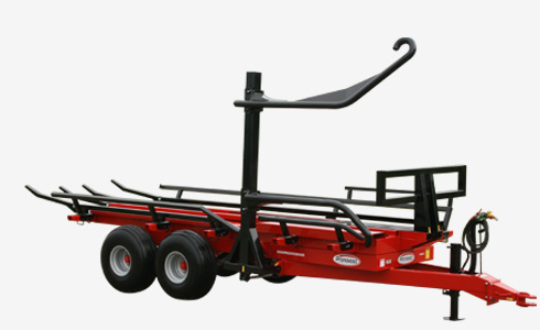
AUTOLOAD ROUND BALE HANDLERS
Please refer to your user manual
For the most accurate and model-specific information, we strongly recommend consulting your user manual first. This document contains details specific to your machine. In case of any discrepancies, the information provided in the user manual takes precedence over that displayed on our website.
SAFETY GUIDELINES
GENERAL SAFETY
- Careful operation is the best assurance against accidents. Carefully read this manual and follow all recommendations before operating your Round Bale Handler. It is the owner’s responsibility to make sure that anyone who will operate the unit will read this manual before operating the equipment.
- Never let a child nor unauthorized persons operate the machine.
- Do not modify the equipment. Any non authorized modification may affect the efficiency and/or safety of the equipment.
- Never operate the Round Bale Handler with defective parts or if damaged in any way. Have it repaired before operating.
- Make sure all fasteners are in place and properly secured or tightened. Refer to torque chart in the user manual.
- Hydraulic fluids under pressure can damage your skin. Do not use your hands to locate a leak. Gloves must be worn.
SAFETY IN OPERATION
- Be sure there are no obstructions around the equipment and that no one stands near the machine when in operation or unloading.
- Be careful when adjusting equipment with engine running.
- Keep your body, hands, feet, hair and clothing away from moving parts.
- Do not stand nor allow anyone to stand under elevated parts of the machine.
- When not in use, always lock the loading arms with the pin provided.
SAFETY WITH MAINTENANCE
- Perform maintenance according to the recommendations contained in the manual.
- Stop engine and relieve all hydraulic pressures before doing inspection, maintenance or repairs.
- Regularly check hydraulic lines and fittings for leaks. Replace if necessary.
- If you must perform work under the raised platform, always block it in position in a safe manner.
SAFETY IN TRANSPORT
- Check local regulations for the transport of your Round Bale Handler on the road.
- Be alert when pulling the Round Bale Handler on the road. Do not allow anyone to stand on it while in motion.
- Be careful while backing-up.
- Ensure that there is no oil circulation in the machine during transport.
SAFETY IN STORAGE
- Lower the loading arm to avoid any accidental crushing.
DECALS
- The safety decals are affixed wherever special safety precautions are indicated. Locate them on the machine and read them carefully. If a decal is damaged, lost or illegible, install a new one.
STARTING-UP THE AUTOLOAD BALE HANDLER
- Oil flow recommended 15 to 18 gal. US / min.
- Lubricate all points with a good quality multi use grease.
- Adjust tire pressure according to manufacturer’s recommendation.
- Install all hydraulic hoses and fittings compatible with your equipment.
- Hook up the Round Bale Handler to the tractor and connect the hydraulic hoses.
- Operate all hydraulic functions in order to purge the system. Do not forget to remove the pin locking the loading arm in the upright position and assure there is no one within 10 feet of the loading area.
- Check the oil level in the tractor’s hydraulic oil reservoir.
- Install hinged bale slides. Insert the bolts so that the nuts are toward the outer side of the bale row to prevent the bale twine from snagging on the nuts.
- Although it is possible to transport an additionnal bale in the loading arm, its weight must not exceed 2000 lbs.
ADJUSTMENTS
– LOADING ARM (Patented)
- Adjust the opening and position of the loading arms according to recommendations. The dimensions given are to be used as a guide only since they may vary according to the bale size, weight and degree of softness.
– SIDE RAILS
- Adjust the side rails position according to the bale size and configuration. This adjustment is to prevent the rocking of the bales from side to side during transportation.
– SWIVEL HITCH ASSEMBLY
- Adjust the swivel hitch assembly to keep the machine parallel with the ground. Three sets of bolt holes are provided to keep the machine level in operation.
OPERATION
- Remember that the Round Bale Handler is designed and built to turn the bales and load them non stop, consequently, the direction of travel will usualy be the same as the baler’s.
- When ready for the first bale, lower the loading arm to just a few inches above the ground, slow down this is a practice round, line up the machine so that the outer corner of the bale will touch at approximately 1/3 to 1/2 way up the angled part of the outer arm.
- Raise the loading arm as soon or slightly before the bale reaches the bottom of the “U”.
- Keep raising the bale until it drops onto the platform. Do the same for loading the second row. Then start lowering the loading arm in order to disengage the limit switch (there is a limit switch installed on the machine, preventing the bale ram and the dumping platform from being activated if the loading arm isn’t lowered enough).
- Once accustomed to the machine and its operation, you will notice that by slightly altering the alignment of the bale relative to the outside loading arm, you will be able to turn it and load it much more rapidly. In this case, the bale should hit the loading arm slightly closer to the heel.
- When the first pair of bales loaded reach the bale supports at the extreme rear end of the platform, an indicator will pop out on the front corner of the platform opposite from the loading arm.
- To unload the bales, simply back up to the area where you wish to deposit the bales, open up the loading arm slightly to clear the platform. Raise the platform fully, then slowly move forward.
- The machine has a ballast support on the opposite side of the loading arm. This support is designed for you to use the weights you have for your tractor. Installation of the weights works the same way as your tractor. This counterweight is useful to load the first bale, to compensate for the lack of weight on the machine. The quantity of ballast to install depends on the mass of the bales.
- Loading techniques:
– If ground is tilted to the right, always return the bale with the outer arm.
– If ground is tilted to the left, it is easier to return the bale with the inner arm.
– The lighter the bale, the harder it will be to return it, because it rolls when arm touches it. To resolve this problem, you simply need to find the right speed for the bale. Heavier bales are easier to handle.
– Be careful; the bale has to be well supported at the bottom of the arms before loading, otherwise it might be badly positioned on the platform and interfere with the pusher or the other bale.
– For manual models, use an hydraulic outlet with a « kick-out » for the pusher to avoid maintaining the « spool » manually.
– For manual models equipped with third row option, it is recommended to use an hydraulic outlet with a floating position in order to allow the loading arm for the third row to go down by itself when pusher comes back to its resting position.
MAINTENANCE OF THE AUTOLOAD BALE HANDLER
The Auto-Load Round Bale Handler is designed to save you energy, time and money, take care of it, protect your investment.
- Wipe off all grease fittings with a clean cloth before adding grease to avoid injecting contaminants.
- Repair or replace damaged grease fittings.
- Lubricate all grease fittings every 20 hours of operation. (Do not forget the Bale Ram, 4 bronze bushings).
- Open, clean and lubricate wheel bearings once a year.
- Check nuts and bolts once a year. If necessary, use torque chart in the user manual.
- Check all bolts on wheels after the first 5 hours of operation and then every 50 hours.
- Check tire pressure every 50 hours. Adjust according to manufacturer’s recommendations indicated on the tires.
- Keep your equipment clean, it is good practice.
STORAGE OF THE AUTOLOAD BALE HANDLER
- Store the Auto-Load Round Bale Handler in a cool, dry place.
- Keep tires off the ground and cover them if left exposed to the sun.
- Keep all piston rods in the retracted position (the loading arm must be lowered). This will assure better protection against the elements. If the chromed rod is exposed to elements, recover it with grease or a rust inhibitor.
- Clean your Auto-Load Round Bale Handler.
- Thoroughly inspect all parts of the Round Bale Handler. Replace or repair worn or defective parts.
- Touch-up or repaint if necessary.
- Lubricate all points before storage.
WARRANTY
PRONOVOST warrants this product to the initial purchaser for the period of one year from the date of purchase against defects in materials and workmanship.
We will replace or repair defective parts free of charge if they are returned to our plant in St-Tite, Quebec, Canada.
Transportation charges are the responsibility of the customer. This warranty is not transferable.
Tires are covered by the manufacturers of these items.
All PRONOVOST spare parts purchased are covered by a three (3) month warranty.
This warranty becomes void and nul if the equipment is modified, breaks down as result of an accident, if not operated according to manufacturer’s recommendations, damaged by negligence or if maintenance has not been carried out as specified.
Our obligation is limited to the replacement or repair of the defective part.
PRONOVOST accepts no responsibility for direct or indirect consequential damages of any kind.
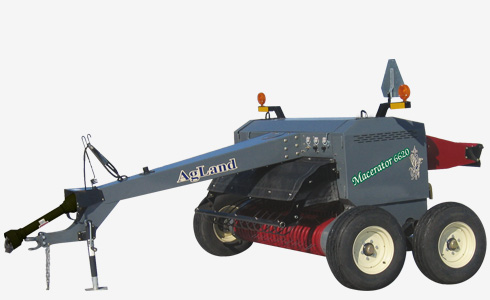
AGLAND MACERATOR
Please refer to your user manual
For the most accurate and model-specific information, we strongly recommend consulting your user manual first. This document contains details specific to your machine. In case of any discrepancies, the information provided in the user manual takes precedence over that displayed on our website.
SAFETY GUIDELINES
SAFETY IN OPERATION
- REVIEW ALL SAFETY INSTRUCTIONS with all operators before allowing them to operate the equipment. Review instructions at least once each year.
- All shields and guards must be intact and in position and securely fastened before operating the Macerator.
- Only use a tractor equipped with ROPS cab and seat belt. Use caution when operating close to a road or building, the machine can throw stones and other objects during operation.
- Emphasize the importance of safety when working around and operating the machine.
- Do NOT allow riders on any part of the equipment at any time.
- Always keep hands, feet, and clothing away from moving parts.
- Always lower the Macerator at ground level when parking.
- Use transport lock pin and retainer to secure the lift linkage of the Macerator before transporting equipment.
- Use safety tow chain at all times.
- NEVER attempt to unplug the machine when the tractor is running and hydraulic system is pressurized.
- Keep hands, feet, and clothing away from the pickup area when in operation to avoid entanglement hazards. Do not open or remove shields or guards while machine is running.
- Remove any pressure in the hydraulic lines before disconnecting them. When applying pressure to the system, make sure that all connections are tight and that the lines are not damaged.
SAFETY WITH HYDRAULIC SYSTEM
- Ensure that all components in the hydraulic system are kept in good condition.
- Replace any worn, cut, abraded, flattened, or crimped hoses and/or metal lines.
- Do not attempt to execute any repairs to hydraulic lines, fittings, or hoses by using tape, clamps, or cements. The hydraulic system operates under extremely high pressure: 1600 to 2300 PSI (11,033 to 15,859 kPa). Such repair will fail suddenly and create unsafe conditions.
- Wear proper hand and face protection (e.g. face shield) when searching for a high pressure hydraulic leak. Use a piece of wood or cardboard as a backdrop instead of hands. A high pressure concentrated stream of hydraulic fluid can pierce the skin. If this is the cas, seek immediate medical attention to avoid an infection or toxic reaction.
- Before applying hydraulic pressure to the system, make sure all connections are tight and that lines, hoses, and couplings are not damaged.
SAFETY WITH AIR SYSTEM
- Make sure all hoses and pads are kept in good condition and are clean.
- Replace any damaged lines or pads.
- Do not exceed 120 PSI (827 kPa) air pressure in tank and 100 PSI (689 kPa) in air bags.
SAFETY IN TRANSPORT
- The operator is responsible for complying with all local regulations regarding the transportation of agricultural equipment on public roads.
- Ensure all signages and reflector as required by local law, are in place, intact, and clean before transporting the machine on public roads.
- Connect the Macerator electrical harness to the tractor’s outlet.
- Ensure SMV emblem is clean and properly displayed, where required by law, before transporting machine on public roads.
- Do NOT allow riders on machine at any time, including transport of machine on public roads.
- Maximum transport speed is 20 MPH (32 km/h). Reduce speed on rough roads and surfaces.
- Use proper retainer on drawbar hitch pin and attach safety tow chain to tractor prior to transporting machine on public roads.
- Ensure that transport lock pin is installed and secured in the hole provided for this purpose.
- Tractor light switches should be set for road transport. Refer to tractor operator’s manual for information.
DECALS
- The safety decals are affixed wherever special safety precautions are indicated. Locate them on the machine and read them carefully. If a decal is damaged, lost or illegible, a new one must be installed.
DRAW BAR ASSEMBLY
Sometimes the drawbar (hitch) will be shipped detached from the unit to allow more compact packaging for shipping and transport.
- Bolt hitch to main frame, using fourteen 5/8” x 1-½” carriage bolts. Ensure all bolts are securely tightened.
- Slide drive shaft onto override clutch. Reinstall bearing and tighten shaft bolts on override clutch.
- Install the long hydraulic hose securely with the clamps provided.
- Torque required on 5/8” bolt for overriding clutch is 65 ft-lbs (88.1 Nm).
FIELD SET-UP
Use with a tractor having a minimum of 80 HP (60 kW) and a maximum of 120 HP. The tractor must have enough land clearance so that the swath can easily pass under the tractor.
PTO SPEED
Units are shipped with either 1000 RPM PTO or 540 RPM PTO speed, according to customer needs. The PTO should run at approximately 1000 or 540 depending on the ordered model. The front rubber rolls will rotate at a speed of 645 RPM, the bottom steel roll runs at 1514 RPM and the upper steel roll runs at 1372 RPM.
PICKUP HEIGHT & ADJUSTMENT
The Macerator 6620 pickup should be adjusted so that it will cleanly pick up all material off the field without gouging the soil. Adjust the pick-up to achieve the correct working height.
- If the pickup is too low to the ground use the tractor hydraulic cylinder control to raise the pickup.
- Remove spring pin and slide adjuster bar to desired height. Pushing the bar inwards will allow the collector to go up and outwards will allow the collector to go down.
- Reinsert spring pin and lock in place.
STEEL ROLL ADJUSTMENT
For best results adjust the Macerator 6620 for your specific field conditions. The smaller the gap between the steel serrated rolls, the more aggressive the maceration of the hay will be. Both the space between the rolls and the air pressure will need to be adjusted for maximum efficiency.
- Raise the Macerator using the hydraulic system.
- Turn crank clockwise to widen the gap or counter-clockwise to narrow the gap. 1 turn = .04” (1 mm). For a better fine tune, adjust bolt.
- Ensure to set the gap exactly the same on both sides, using a gauge, as shown on figure 12.
- Put crank lock in place and secure with spring pin.
- To ensure that the rolls do not touch, the safety stop is set at the factory at 1/32” or .8 mm.
- If the safety stop needs adjusting put the travel pin in place while unit is raised.
- Adjust the safety stop bolt as needed. Ensure the rolls do not touch during operation.
- Repeat steps 1–7 to fine tune if necessary.
PREPARATION (AIR SYSTEM)
The purpose of the air system on the Macerator 6620 is to keep continuous pressure on the rolls. The pressure can make a difference on how well the machine performs on the field. While the pressure on the rubber rolls may not be as crucial, too much pressure on the steel rolls will result in considerable leaf loss and some plugging may result in short wet hay. Before heading out to the field, ensure the air pressure tank has a minimum of 100 PSI (689 kPa) pressure. Not to exceed 120 PSI (827 kPa). This should give the operator sufficient air supply for the day.
RUBBER ROLL PRESSURE ADJUSTMENT
The rubber rolls are designed to take the material from the pickup and feed it into the steel rolls. The rubber rolls do not crush or crimp the hay.
As a standard setting, we recommend 20–30 PSI (138 – 207 kPa) pressure on the rubber rolls. Regulate the pressure by pulling out the knob on the regulator marked ‘rubber rolls’ and rotate it clockwise or counter-clockwise. When turning the knob counterclockwise the sound of air escaping from the regulator should be heard.
In extreme conditions, increase or decrease the pressure. For example, very heavy swaths may require more pressure.
STEEL ROLL PRESSURE ADJUSTMENT
The steel serrated rolls (rear) take the material from the rubber rolls and crack the stems. To achieve the right setting, some field testing may be necessary.
- Pull out the knob on the air regulator marked ‘steel rolls’ and rotate the knob clockwise or counterclockwise to set the pressure of the steel rollers to approximately 5-35 PSI fo alfalfa and 40 80 PSI for all other types of fodder.
- Lower the Steel Roll Air Pressure by pulling the Relief Valve Ring at top of Left Side Air Bag to relieve pressurized air. (Ensure the Pressure Valve Knob is pulled out and turned all the way counter-clockwise before relieving air from the bag.) Repeat pressure setting as in step 1 above to set a new air pressure.
- If there is too much leaf loss or excessively split stems, decrease the air pressure.
- If there is not enough maceration, increase the pressure of the steel rollers by increasing the air pressure. Make sure the gap is adjusted.
Note: Steel Roll Pressure should not be set higher than 65 PSI (448 kPa) at any time during field operation.
FOR OPTIMUM USE
Good preparation of the machine and a good management of the forage operations will ensure efficiency and optimum performance. The Macerator is a very technical machine, this is why we recommend that you follow these recommendations to get the maximum from it.
During operations, we recommend that you perform mowing at the end of the day. The sugar level in the plant is higher, therefore more profitable for your animals. In addition, this will allow the hay to keep its beautiful green color, since the bleaching due to sunrays which directly strike the grass in broad daylight will be greatly reduced at the end of the day. Avoid producing swath wider than the distance between your tractor wheels. This way, you will not roll on the swaths and avoid burying forage into the ground.
Once all the adjustments of the Macerator have been made on the farm, as presented in this manual, all that remains is to make the correct pressure adjustment on the rollers. Make sure to have a pressure of 100 psi in the tank to be able to work without any problems. There is no exact rule to determine the pressure, you have to try with a starting pressure and use the machine on 30-40 meters to determine if maceration is sufficient or not. The suggested starting pressure is 20 psi for rubber rolls and 0 psi for steel rolls and then increase pressure if necessary. It is important to adjust the pressure of the rubber rolls at least at 8 psi more than the steel rolls. This will avoid a premature wear of the rubber rolls and allows a better performance of the steel rolls. To determine if maceration is sufficient, take macerated hay and look the rate of scratches on the plant. When around 75% of the plants are scratched, maceration is sufficient. Use the Macerator early in the morning, when dew is still on the ground. The earlier you start and the earlier you’ll be done, the more the effect of the Macerator will be felt on the plant for the rest of the day. Thus, you will also help to avoid the accumulation of plant wax on the rollers. To increase operation efficiency, it is recommended to use the Macerator in the same way as the mower, this allows the forage to enter the machine easily and avoid risks of jam. We recommend you finish by the swaths at the end, because at every turn at the end of the field, you roll on them. By finishing with the ends of the field, you will get the buried hay out and the Macerator will clean it by shaking the hay, which will remove dirt and ashes that has entered the swath. Speed is very important. It will depend on the width of the swaths, the dew and the field conditions. Usually, going at the speed of the mower is a good starting point, then you can adjust your speed to surrounding conditions. Scientific studies have shown that a single pass of Macerator was more effective for the first cuts of hay made at the start of the season, while two passes of Macerator gave better results for the later cuts at the end of the season. After using the Macerator, it’s enough to pass a rake and under good conditions, the hay can be ready cllect at the end of the afternoon on the second day.
IN THE CASE OF A JAM…
- Stop the PTO.
- Stop tractor engine.
- Raise the machine.
- Remove air from rubber rolls.
- Take the shaft (located inside, on the right side of the machine).
- Place the key on the nut (A) of the big pulley (same side as the shaft) and turn the machine counter clockwise.
MAINTENANCE OF THE MACERATOR
CHECKLIST
Use Good Safety Practices When Working On This Machine
Before doing any maintenance or service on the machine you must:
- Park machine on a solid level surface.
- Lower the machine fully to the ground or onto blocks.
- Disengage all power.
- Put the tractor transmission in PARK or apply the tractor parking brake.
- Stop the tractor engine and remove key from the ignition.
- Observe and listen. Make sure all moving parts are not on.
FIRST TIME USE
- Tighten hub bolts after the first one (1) hour of operation and repeat procedure after ten (10) hours and fifty (50) hours.
DAILY
- Check and tighten all hub bolts.
- Remove all dirt and crop deposits from the machine.
AFTER THE FIRST TWENTY-FIVE (25) HOURS OF USE
- Check bearing and set screw tightness.
AT THE BEGINNING OF EACH SEASON
- Review all safety instructions.
- Carefully inspect all components for excessive wear or hazardous conditions.
- Lubricate the machine at all lubrication points.
- Check tires for correct inflation pressure.
- Tighten bolts.
ROLL DRIVE BELT REPLACEMENT
Replace worn or damaged belts as follows:
- Raise Macerator and secure travel safety pin.
- To remove belts loosen and turn flattened bolt counter-clockwise.
- To remove belts loosen 4 bolts, then loosen bolt and slide roll forward. To maintain proper roll alignment be sure to adjust the opposite tightener on the other side of the machine.
- To remove belt loosen bolt behind tightener, then loosen bolt and slide tightener forward.
- To remove belt loosen bolt on the other side of the panel behind tightener. Take tightening wrench (use a pipe for leverage) and hold spring tightener firmly in place while loosening bolt, then release tension slowly with wrench.
- Replace all belts and tighten bolts (reverse sequence of steps 2 to 5).
- To remove belt loosen spring tension by turning off nut counter-clockwise. To tighten the strap, tighten the nuts until the measurement is approximately 1 1/2″ (L) or at the proper tension on the strap.
- Reinstall all covers.
BEARING REPLACEMENT
Sealed ball bearings are held in position on the shaft by a locking collar which is rotated to lock the assembly on the shaft and secured by a set screw. To remove bearing:
- Loosen set screw.
- Use a drift punch inserted in the drift pin hole to rotate and loosen the locking collar. Rotate the locking collar counter-shaft rotation.
- Remove the locking collar.
- Support the shaft, for easier assembly later.
- Remove the bolts for the bearing flanges.
- Slide the bearing and the flanges from the shaft.
Note: Cleaning paint and corrosion from the shaft will make removal easier. - Put on the new bearing and flanges.
- Replace locking collar on the shaft. Pivot the locking collar in the direction of rotation of the shaft until a slight engagement is obtained. Tighten the locking collar by hitting it with the punch inserted into the pin hole while pivoting it further until it is fully tightened.
- Tighten set screw.
REPLACING OR REPACKING WHEEL BEARINGS
- Remove wheel hubs and disassemble.
- Clean bearings, seals, caps, washers, nuts, and hubs with kerosene or other solvent.
- Replace bearings or seals if worn or damaged.
- Pack bearing cones and seals with No. 2 multipurpose lithium grease or equivalent.
- Reassemble hub and bearings.
- Press cups (race) against the shoulder in the hub.
- Push the seal flush with the hub after inserting the bearing into it.
- Place hub on shaft taking care not to damage the seal.
- Tighten the wheel bearing nut. Do not overtighten.
- Secure nut with a cotter pin.
- Make sure to replace hub cap.
PICKUP TEETH, WRAPPERS, AND WEAR STRIPS
Check for bent, broken or loose parts. If necessary, replace teeth or related parts. Proceed as follow.
- Ensure that the Macerator is blocked securely. Loosen the bolt holding the wrapper(s) on the pickup. Lift the wrapper on top, tilt and slide forward to remove.
- Should the plastic wear strip require removal and replacement, drill out or carefully grind off the ‘pop’ rivets. Replace strip with new rivets.
- Install new teeth or wrapper(s).
TORQUE CHART FOR BOLTS AND NUTS
Use the tables in your user manual as a guide when tightening bolts and nuts that have no pre-specified torque requirements.
LUBRICATION OF THE MACERATOR
GENERAL INFORMATION
A NLGI No. 2 multi-purpose high temperature lithium base grease is recommended.
Use a manual grease gun for all greasing. Air powered grease guns may damage the seal on the bearings.
Wipe all grease fittings with a clean cloth before greasing to avoid injecting dirt or grit in the bearings.
AT THE BEGINNING OF THE SEASON
Grease all sealed bearings, front rolls (two places), rear rolls (two places) and drive shaft (one place) every 50 hours. One shot.
Thereafter, grease all sealed bearings and universal joints weekly or every fifty (50) hours. Bushings and axle bushings daily or every ten (10) hours.
It is recommended that the steel roll bearings be changed every 3000 acres or yearly.
It is also recommended that the pickup cam follower bearings be changed on a yearly basis.
Rotate the entire system using the reversing wrench to make sure the belts are not stuck in the pulleys. This will prevent the tractor from doing so, which could damage the belts if they were stucked.
AT THE END OF THE SEASON (STORAGE)
Wash the machine, but avoid wetting on the bearings.
Then turn on the machine for 15 to 30 minutes to dry bearings and belts.
Remove tension on all belts. Empty the air tank almost completely, but keep enough air in the system to avoid air bushing to collapse and create distorsion of the bushings over time.
Remove all hydraulic pressure.
TROUBLE SHOOTING
| PROBLEM | POSSIBLE CAUSES | CORRECTIONS |
|---|---|---|
| Pickup is skipping swath or not picking cleanly. | Missing or broken pickup teeth. | Replace missing teeth. |
| Pickup too high. | Adjust pickup height. | |
| Forward speed too fast for pickup speed. | Use lower tractor gear with higher RPM. | |
| Does not follow the same direction as the swath cut. | Follow same direction as swath cut. | |
| Material wrapping in pickup. | Pickup running too low. | Set pickup teeth 1” to 2” above ground. |
| Pickup and travel speeds are not equal. | Match pickup and ground speed as close as possible. | |
| Breakage or bending of pickup teeth. | Running pickup too low. | Adjust pickup height. |
| Excessive pickup rotation speed in rough or rocky conditions. | Reduce pickup or ground speed. | |
| Excessive noise or heat from gear box. | Insufficient oil in gear box. | Top up gear oil as needed. |
| Worn or broken parts inside gear box. | Replace parts as needed. | |
| Air pressure does not hold in air tank and air bags. | Broken air line. | Repair or replace line as needed. |
| Torn or punctured air bag. | Replace air bag as needed. | |
| Air regulator not working. | Clean or replace regulator. | |
| Pickup does not go up or down. | Worn or punctured hydraulic cylinder or hydraulic oil line. | Replace hydraulic lines and cylinders as needed. |
| Bushings too tight. | Replace or clean bushings. | |
| Pickup height adjustment does not hold. | Broken or worn parts on adjuster. | Replace worn parts as needed. |
| Missing pin. | Replace worn parts as needed. | |
| The rubber rollers do not feed properly. | Air pressure too high or low. | Adjust air pressure using regulator. |
| Gap between rolls too tight or too wide. | Adjust gap width. | |
| Wax buildup on steel rolls. | Temperature and hay conditions cause the wax to come off of the plant and stick to the rolls. | The wax will come off after the rolls cool down. |
| Excessive leaf loss. | Too much air pressure on steel rolls. | Release air pressure. |
| Hay conditions too dry. | Condition hay early in the morning. | |
| The gap between steel rolls is too narrow or the rolls are going too fast. | Adjust gap between steel rolls. | |
| Hay is not being macerated. | Not enough air pressure on steel rolls. | Adjust air pressure as required. |
| Gap between rolls is too wide. | Narrow the gap between steel rolls. | |
| Swath is too thick. | Cut the swath wider or thinner. | |
| Steel rolls not running fast enough. | Increase tractor RPM. | |
| The swath is not completely inverted. | Moldboard is not adjusted properly. | Adjust moldboard angle. A tighter angle will result in less inversion. A wider angle will result in a greater inversion. |
WARRANTY
Les Machineries Pronovost inc. (hereinafter called “Pronovost”), manufacture the Agland Industries Macerator. Pronovost warrants to the original owner of the AgLand Macerator that the Macerator is free of defects in material or workmanship. This warranty is limited to 1 year from the delivery date to the original owner.
The manufacturer’s obligation in accordance with this warranty is limited to the repair or replacement, at the manufacturer’s choice, of parts or parts of the unit which prove, according to the manufacturer’s judgment, to be defective in material or equipment, a manufacturing defect. At its discretion, Pronovost reserves the right to repair or replace, in whole or in part, any defective part.
Warranty service may only be performed by an authorized Pronovost Dealer or an authorized Pronovost Service Centre or as determined by Pronovost. Transportation charges are at the expense of the retail purchaser. Defective parts must be returned to the Manufacturer or the AgLand Dealer who sold the Macerator at the expense of the retail purchaser and are to be inspected by the Manufacturer.
Note: The retail purchaser’s sole remedy to claim under this warranty is the repair or replacement of defective parts.
Pronovost does not accept any responsibility for incidental or consequential damages of any kind, or loss of income for all equipment under this warranty coverage.
The Macerator is warrantied for normal agricultural use only. This warranty does not cover claims resulting from operations other than agricultural applications.
Any available warranty will be void if: a) Maintenance procedures are not followed in accordance with the guidelines in the Operator’s Manual; b) Any altering or modification is performed on the Macerator which is not approved by the Manufacturer; c) Any additional equipment is installed on the Macerator which has not been approved by the Manufacturer; d)The instructions given in the operator’s manual are not followed during the mounting or assembly of accessories and regular maintenance; e) If the failure is caused by improper operation not in accordance with the instructions; f) If the failure is caused by an accident; g) If the failure is
caused by negligence or abuse; or h) Any claim made under this warranty by, or for, a person other than the original owner.
All Pronovost original spare parts purchased are covered by a three (3) month warranty.
Note: All parts NOT manufactured by Pronovost carry their own manufacturer’s warranty. The customer is responsible for all costs necessary to replace those parts unless covered by the applicable manufacturer.
There are no other warranties, expressed or implied, by Pronovost or its Dealers regarding the AgLand Macerator except the warranty expressed herein.
No person is authorized to bind Pronovost to any other warranty whatsoever.
Pronovost reserves the right at any time to make changes or improvements to the design, materials, or specifications of the Macerator or parts without thereby becoming liable to make similar changes to the Macerator or any of its parts previously manufactured.
MULTIMIXER
Please refer to your user manual
For the most accurate and model-specific information, we strongly recommend consulting your user manual first. This document contains details specific to your machine. In case of any discrepancies, the information provided in the user manual takes precedence over that displayed on our website.

SAFETY GUIDELINES
GENERAL SAFETY
- Careful operation is the best assurance against accidents. Carefully read this manual and follow all recommendations before operating this equipment. It is the owner’s responsibility to make sure that anyone who will operate the Mixer will read this manual before operating the equipment.
- Do not modify the equipment. Any non authorized modification may affect the efficiency and/or safety of the equipment.
- Never operate the equipment with defective parts or if damaged in any way. Have it repaired before using it.
- Make sure all fasteners are in place and properly secured or tightened. Refer to torque chart in the user manual.
- Hydraulic fluids under pressure can damage your skin. Do not use your hands to locate a leak.
SAFETY IN OPERATION
- WARNING! Do not overload your mixer, do not exceed the load capacity indicated in the specifications in the user manual.
- Do not operate an engine in a confined or non ventilated area.
- Do not perform any adjustments, maintenance or repairs with the engine running on the carrying vehicle. Preferably remove the key from the ignition.
- Apply parking brake while filling the mixer.
- It is recommended to stop the rotation of drum when filling in order to avoid injuries.
- Be careful when backing-up, make sure you have good visibility.
- Always travel at a safe operating speed following regulations and common sense. The road speed should be such as to maintain full control over steering and braking.
SAFETY WITH MAINTENANCE
- Perform maintenance according to recommendations contained in this manual.
- If the mixer is hooked up to the tractor while performing maintenance work, make sure the engine is not running and preferably remove the ignition key.
SAFETY IN TRANSPORT
- Be alert while driving on the road. Never carry passengers.
DECALS
- The safety decals are affixed wherever special safety precautions are indicated. Locate them on the equipment and read them carefully. If a decal is damaged, lost or illegible, install a new one.
STARTING-UP THE MULTIMIXER
- Adjust chain by adding or removing shims under hydraulic motor.
- Lubricate chain.
- Install all hydraulic hoses and fittings compatible with your equipment.
- Verify for adequate tightness of all fastening devices. Refer to torque chart in the user manual.
- This mixer has the capacity to mix from 1 to 1.5 bags of cement.
- To empty the mixer, just reverse rotation of drum.
MAINTENANCE OF THE MULTIMIXER
- Lubricate chain every 40 hours of operation.
- Check chain tension every 40 hours of operation, and adjust if necessary.
- Check hydraulic motor mounting every 40 hours of operation.
- Wash mixer after every use.
- Check all nuts and bolts once a year. If necessary use torque chart in the user manual.
STORAGE OF THE MULTIMIXER
- Store in a fresh and dry place.
- Clean your mixer.
- Thoroughly inspect all parts of the mixer. Replace or repair worn or defective parts.
- Touch-up or repaint if necessary.
- Lubricate chain before storage.
WARRANTY
PRONOVOST warrants this product to the initial purchaser for the period of one year from the date of purchase against defects in materials and workmanship.
We will replace or repair defective parts free of charge if they are returned to our plant in St-Tite, Quebec, Canada.
Transportation charges are the responsibility of the customer. This warranty is not transferable.
Hydraulic cylinders are covered by the manufacturer of these items.
All PRONOVOST spare parts purchased are covered by a three (3) month warranty.
This warranty becomes void and nul if the equipment is modified, breaks down as the result of an accident, is not operated according to manufacturer’s recommendations, damaged by negligence or if maintenance has not been carried out as specified.
Our obligation is limited to the replacement or repair of the defective part.
PRONOVOST accepts no responsibility for direct or indirect consequential damages of any kind.
GENERAL INFORMATION
POWER TAKE OFF WARRANTY
The PTO shafts are warrantied by the manufacturer. This warranty covers only manufacturing defects in the material and workmanship. It is conditional to recommended use and installation only.
The life expectancy of a PTO shaft including components such as yokes, u-joints and tubes depend on many factors which cannot be controlled by Les Machineries Pronovost inc.
Factors directly affecting the life of a PTO shaft :
- Pronounced working angle.
- Angle of the snowblower to the ground.
- Frequency of lubrication and grease type used.
- Intermittent or continuous work cycle.
- Proper usage by the operator.
- Speed of rotation.
Should one or more of the above situations apply, our snowblower price list offers a range of optional solutions :
- Upgrade PTO shafts.
- PTO shafts with Multilobe Tubes.
- Installation of the snowblower at 1000 RPM instead of 540 RPM with the use of a reduction gear box to decrease the angle of the PTO shaft and / or decrease the load on the tractor’s transmission.
IMPORTANT: When using a 1000/540 speed reducer, be sure to use a 10 mm shear bolt or a 12 mm shear bolt reduced to 3/8″ according to model of drive shaft (PTO).